Main Content

Landing page for projects I am working on (for fun). Or concepts that need discussing, ect. Web items are found under the hamburger menu, and will receive their own entries. Eventually.


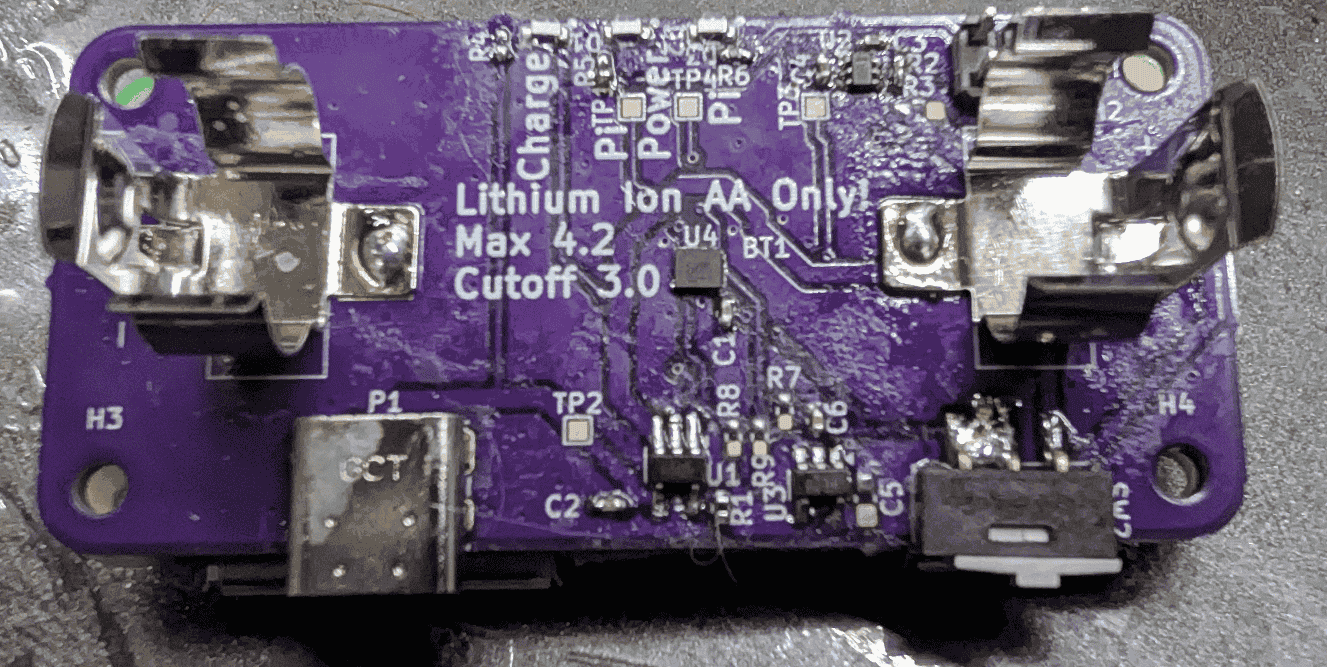
As a first pass, the goal here was to ensure fitment, rough operations, and suss out any issues with the board or design. The goal here is to be a Rev1, for a future Rev2, but confirm the battery charging, load switch, and board fits perfectly with the Raspberry Pi 2W. The board was designed to have a physical cutoff switch, and a holder for a 14550 (AA) sized cell, with a few side mounted LEDs for status, and to mount directly using the top 6 pins to deliver power through the header of RPI 2W. Additionally, the charger was designed such that if the cell began to degrade, or a near-dead cell would be inserted, it would attempt to trickle charge until a safe level was attained and have full battery detection while maintaining full battery, all of which charged over USB. Overall project can be found in this git repo, under the "EE" folder.
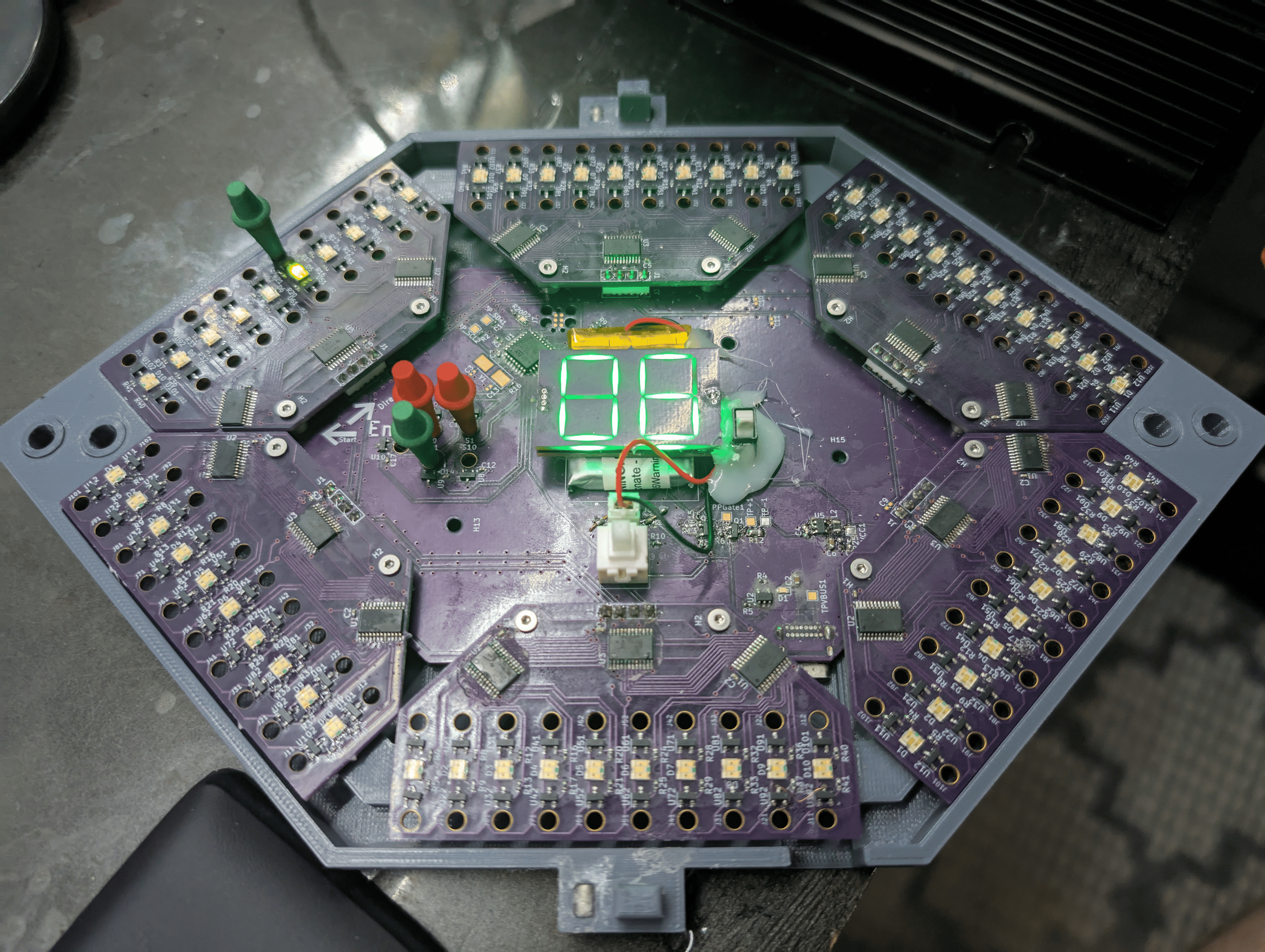

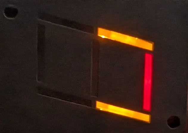
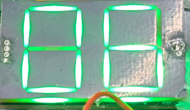
This is a look into the development of a dialightbulb used for the Dialco 7 Segment product line. Mostly is a simple exercise in PCB design, and reducing cost, but is mostly surrounding mechanical placement, non-standardized parts, and production yields.

With the loss of the RGB 7 Segment offering from Adafruit, there became a distinct lack of RGB 7 Segments. So I took it upon myself to come up with some form of new LED, as it was necessary for a more compact implementation on my Cribbage Board. The goal was to reduce the BOM / Suppliers as much as possible, so the diffuser was also built out of a PCB. The original ideas were to use WS2812-esque LEDs, to be 7 discrete LEDs per segment, but still expose at most 4 pins (Power, Ground, Data, Clock). Additionally using solder and fine pitched headers allows for easy placement / affixing of diffusers as opposed to other mechanisms.