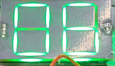
RGB 7 Segment
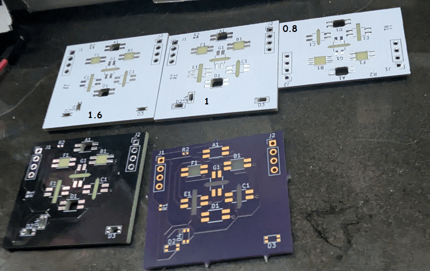
Considering no vendor (that I found) exists to still sell RGB 7 Segment displays, I took it upon myself to make a PCB sample variants, and try out a few topologies to test out. First, I got a bunch of boards made from PCBWay, with varying PCB heights to test the pass through capabilities of light, and see if the solder mask color played a part in overall appearence. In the below, there were three different PCB widths (minimum being 0.8mm, max being the typical 1.6mm), as well as comparing white solder mask to black solder mask, to see if the light appeared "better". From this, the exact thickness did appear to help a little bit, but still ahd issues with diffusing. Overall darker solder mask did have a better appearence due to the stark contract.
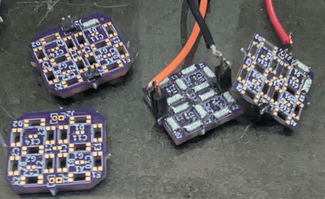
After doing some very manual testing of literally placing an LED up to the gaps (roughly soldered and pressed), it kind of appeared that that piece didn't fully matter for these specific LEDS (Digikey PN: 1528-4960-ND). Additionally, I did some testing to determine if changing the width of the negative of the solder mask would apply a lot or not on appearence. Which sure it did, but it never quite looked... right as it kept making hotspots. A lot of this testing was done with the idea of reverse mounted LEDs, to pump RGB LED light *through* the PCB from an LED soldered to the same PCB. No picture seen here, but it would always create a clear bright spot, and would not diffuse evenly. These LEDs were designed to have a slot cut and pump through the channel, whereas I attempted without the cut.
This prompted the further testing, as the passthough of this particular LED did not appear very qualitatively "good", and this variety of RGB LED has the weird timing requirements that necessities tight parameter tuning of an MCU (e.g. WS2812). With the confluence of these two issues, I re-attempted the thought process of using another variety of RGB LED but instead of mounting normally onto a PCB, I attempted *through* the PCB even though the LED was not intended to do this. The LED chosen for this is from Everlight (Digikey PN: 12-23C/RSGHBHW-5V01/2C). While this technically did work, the soldering of the device was not very successful. The mechanical drawings provided for this LED were not *quite* sufficient to give a proper size cutout, reliably, to mount the LED improperly like this.
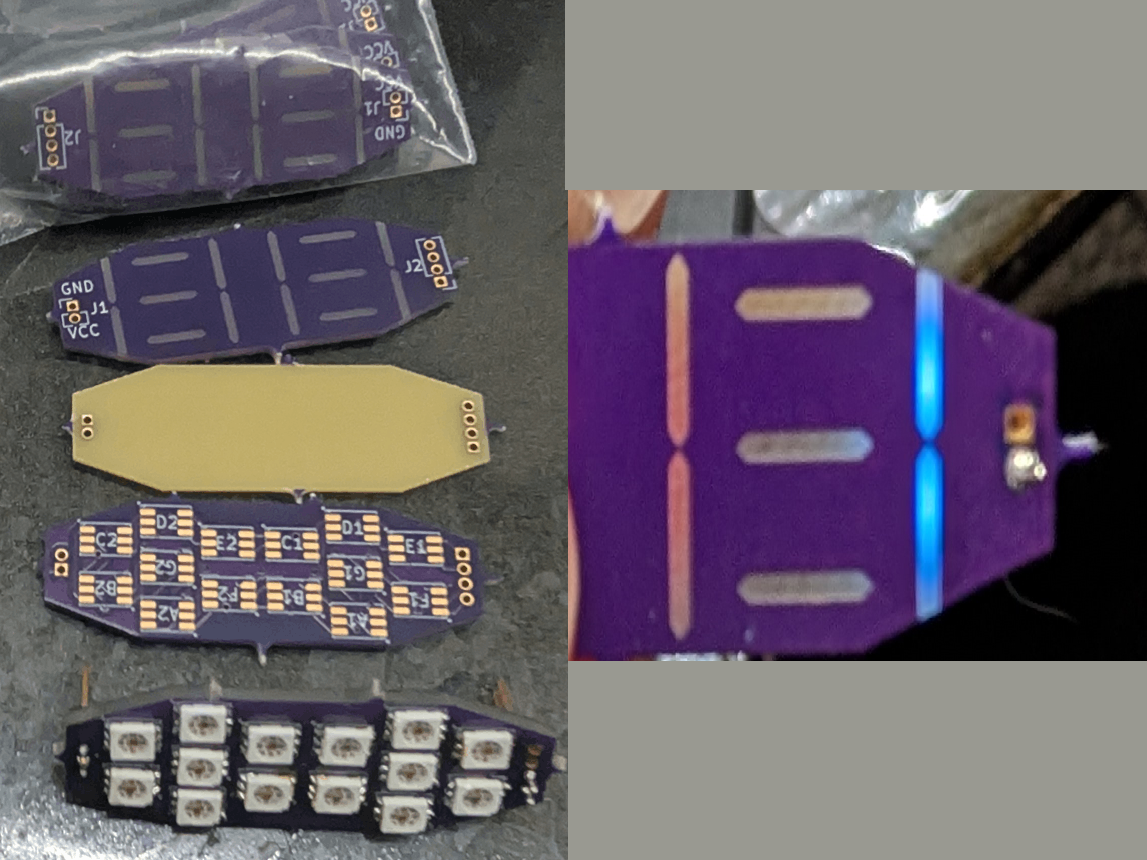
The most recent incantation of the design, was a move to using a 6 bin, normally mounted LED (Digikey PN: 587-2086-247F). This particular LED used a more traditional SPI Bus, but passes along the next data packet and clock after the correct amount of bits are received. This allows a more generic interface to be used, and not require weird DMA interfaces with weird timing. This paradigm is what ended up being used in the Cribbage Board, but more work was done to test out the diffusers. The end result here still is not quite right, as users of the system can't always fully see *what* is being displayed at any given time. Untrained eyes sort of problems. An additional spin of the diffuser at 0.8mm, and the base PCB at the same was done, yet has not been soldered nor tested yet. Below is pulled from the cribbage board to show its current appearence, with the two 1.6mm boards.